So I am undertaking this conversion on my MGF.
I am also trying to finish that never quite finished How-To on how this can be done for our MGFs. I see lots of information about which answers some but not all questions, which I hope to resolve by this post...
I myself have one final question before I put up the parts list, ecu connectors both from the EU2 and EU3 point of view, so that you can easily search and cross references wires from both ends of the version.
For now I only have one question remaining..
If you look at a MGF circuit diagram in either EU2 or EU3 mode with ABS and non ABS.
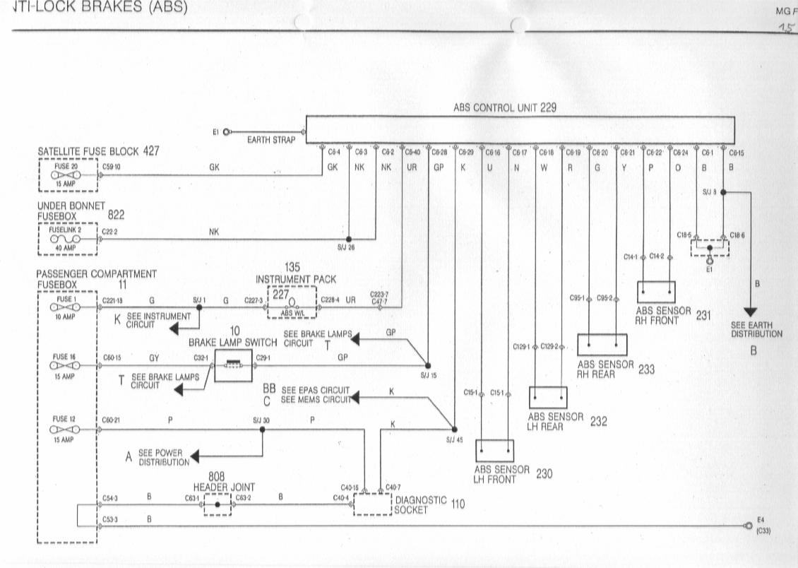
- With non ABS its a red wire from the LH rear abs sensor
- With ABS its a slate and black wire coming from it says P23 of the ABS module at the front of the car
Both of these connect to Pin78 of Connector C0159 - the smaller ECU plug.
Now I know that the car will run just fine without it, it will just report random misfires on occasions when it shouldn't.
MGF and MGTF have same abs wiring diagram - which can be seen here, reference the ABS page.
https://www.the-t-bar.com/community/dow ... l-diagrams
First thing is when I check my MGF its not the same ABS unit - its defo doesn't have the same 3 row connector with 31 pins, its got more in only a 2 row format... I will upload pictures in a second.
I think it matches this EU2 ABS pin wiring shown here...
http://mgfcar.de/schedules/sb15.jpg
Next the wiring in my EU2 connector doesn't not contain a return wire to the ECU other than the K diagnostics line as far as I can see... Now this agrees with the EU2 vvc diagram which appear to only show this wire linked for automatics - so it looks like MEMS2J didn't expect to receive this signal but I want to double check this.
Maybe there is a pin out on this ABS ecu which allows for this information to be returned, if so which pin on this older ABS unit is it, and which colour - its not there by default it would appear....
On non-abs models it comes from the LH rear abs signal (rough road speed sensor) so is it possible to just splice into this red line and send it instead...
I have read that the number of signal changes / counts are different something like 800 vs 3000 per mile so do i need to update the ecu if I did this modification?
Has anyone completed the MEMS3 upgrade on an ABS vehicle, and then connected this misfire speed signal, to this older type of ABS unit.
Anyone any other ideas on this one.... For now I may leave the wire blocked off but outside the main plug so I can add to it easily in future, but for now it will run just fine without it- I just wanted to finish off the picture...
143vvc - 160 MEMS2J -> MEMS3 conversion
Moderator: Committee Members
Forum rules
Not many rules really, this board being aimed at technical issues, it shouldn't fall foul (hopefully) of some of the more personal issues that can affect forums.
Rule 1 - Is that you need to think very carefully before posting anything technical or asking anything technical relating to the security system of the car - See 'Security Issues' sticky for more info.
Rule 2 - We (MGF Register) do not support copyright infringement and therefore references to CD ROM, PDF versions or paper copies of the workshop manual (for instance) should not be posted on the forum. We don't want to get into trouble and we'd rather sell you a genuine hard copy through our Regalia shop anyway!
Because advice is honestly and freely given in this technical section, much of it will be amateur experienced based, so any information is given in good faith and is not guaranteed as correct.
-
trevor.getty
- Posts: 16
- Joined: Wed Apr 29, 2020 6:38 pm
- MGF Register Region: Elsewhere
143vvc - 160 MEMS2J -> MEMS3 conversion
Last edited by trevor.getty on Thu Jun 04, 2020 4:27 am, edited 1 time in total.
-
trevor.getty
- Posts: 16
- Joined: Wed Apr 29, 2020 6:38 pm
- MGF Register Region: Elsewhere
Re: 143vvc - 160 MEMS2J -> MEMS3 conversion
Ok lets start with what parts are required before i get into the how to...
Required:
- 160 Inlet manifold
- 160 blue injectors
- All manifold sensors tmap / iacv / air tmp sensors ( hopefully just buy a full manifold with everything on it. )
- Oil Temp sensors ( I installed from a mems3 car entire filter housing with sensors ).
- oil temp sensor for both ECU ( 4 pin type )
- and oil temp for the gauge.. note if leaving old oil temp gauge I left my old sensor to match up.
- Coolant sensors ( again I just entire arm off a later mems3 1.4 engine ).
- 160 ECU set ( immob / ecu / fob.. ) now you can use just the ECU and get it mapped to repair with your existing one, or turn off immob ).
- MEMS3 MGF loom
- Either MEMS3 - 160 VVC loom, or 120 /135 MPI loom.
**The later 160 VVC loom doesn't match in all its ancillaries, like starter has different connections etc.
I actually used a MEMS3 MGF loom which had all matching connections and added VVC sub loom to it.
So its up to you which way you go here.
- Optional:
- If you get the 160 VVC loom you may need to get matching alternator with matching plug from later MEMS3 VVC MGF / TF.
- As I opted for non vvc loom I didn't need any other parts, but I did need to make or extract a VVC sub loom for its connections.
- I have a separate "how to" - on adding a VVC sub loom to your normal MPI MEMS3 loom - specifically for use on an MGF car with its own specific wiring colours.
- Here is a "how to make a VVC subloom and add it to your MEMS3 MPI loom" by Andrew specific for use on Caterham K Series. ( http://andrewrevill.co.uk/LoomConversions.htm )
- Optional:
- MEMS1.9 or MEMS2J spare loom.. I bought a 2J loom as I could take both the VVC subloom and also the EU2 connectors from it for my hybrid loom.. But you can use your own cars MEMS2J loom but I didn't want to take my car off the road while doing all this preparation work.
Optional:
- Mems3 160 coil packs *2 ( on top of the car type ).
- Mems3 VVC HT leads from coil packs *2
- Mems3 Cam cover ( all the same so doesn't need to be VVC ), just allows coils to be secured on top
- Mems3 Rocker cover plastic - not the old one has a cover in the middle for the 4 cables get a later cover.
These are all optional as you can alter the mems3 wiring and splice off to the older coil packs, which will work just fine.
Notes:
I recommend using the 160 VVC loom matching your car model... For my case this was an MGF, and this is what my how to will be specific to, using colours from early EU2 and later EU3 MGF specs.
If not you can get into colour nightmare - my how to will help with every required pin out but you could be splicing a lot of mixed colours which makes it harder when / if issues arise .
Also stay away from using a ZR160 loom, of course you can make the engine work - follow my pin outs and add what you need and the engine will run just fine.. But items such as required engine bay fan driver isn't within the loom or the ECU itself. As such you will have to rewire your engine bay fan to operate like the later MG TFs do, which is to come on in parallel with the main coolant fan.
Go and gather up all these parts and come back when you are ready .....
Re: 143vvc - 160 MEMS2J -> MEMS3 conversion
You might consider going to your local Scrappie, buy a Mems 3 car and arrange to strip out all the required bits and then sell the car back.
I did this in 1970 when I had a gearbox failure that took out the engine on my Austin 1300.. The job was done in their yard even using their crane. Out Saturday, in Sunday.
Geoff.F.
I did this in 1970 when I had a gearbox failure that took out the engine on my Austin 1300.. The job was done in their yard even using their crane. Out Saturday, in Sunday.
Geoff.F.
-
talkingcars

- Posts: 5771
- Joined: Tue Mar 09, 2010 10:44 pm
- MGF Register Region: South East
- Model of Car: mk1 VVC
- Location: West Sussex
- Contact:
Re: 143vvc - 160 MEMS2J -> MEMS3 conversion
Following with interest as this may be something I do one day, I have many of the parts around to do it.
A couple of comments - the extra line out of the later alternator is to the ECU so it can alter the engine map on the engine in the case of a high load from the alternator, it can be left out. Conversely if you need to change the alternator a later one can be fitted to the earlier car just modifying the wiring.
The main difference on the MEMS 3 inlet is the addition of an extra sensor (vacuum IIRC) which, with carful drilling, can be added to an earlier inlet manifold.
MK1 cars don't have a post cat lambda sensor. You can either add one by changing the cat and exhaust or just get it mapped out of the ECU. It doesn't effect the running anyway, it's just to tell the ECU that the cat is cleaning the exhaust correctly.
James
Home to black Alfa 159 3.2 V6 Q4, blue MGZR160, green MGF VVC and grey MGF 1.8i, and red MG Maestro T16.
MGF chatting on the Register and at http://www.the-t-bar.com
MGF chatting on the Register and at http://www.the-t-bar.com
-
trevor.getty
- Posts: 16
- Joined: Wed Apr 29, 2020 6:38 pm
- MGF Register Region: Elsewhere
Re: 143vvc - 160 MEMS2J -> MEMS3 conversion
When you have a limited edition car, like my no3 abingdon MGF VVC, I want to keep the dash non electric and original as possible. This change isn't being done for power, and the entire engine itself is kept as is.. I am doing this for the ability to look after my car for years to come.Geoff.F wrote: ↑Sat May 30, 2020 1:08 pmYou might consider going to your local Scrappie, buy a Mems 3 car and arrange to strip out all the required bits and then sell the car back.
I did this in 1970 when I had a gearbox failure that took out the engine on my Austin 1300.. The job was done in their yard even using their crane. Out Saturday, in Sunday.
Geoff.F.
Changing over to the later MEMS3 wiring loom to the interior dash is almost as much work as the rear engine loom conversion ( its not easy on the mgf ), and to be honest I would never want to move over to the later digital dash.
So I am left with keeping my entire car original and just moving the ECU over to mems3 which I am trying to do, with some additional sensors of course.
-
trevor.getty
- Posts: 16
- Joined: Wed Apr 29, 2020 6:38 pm
- MGF Register Region: Elsewhere
Re: 143vvc - 160 MEMS2J -> MEMS3 conversion
Correct the extra line out of the altenator can be left off, but the wiring is 10mm nut not 8mm, so its needs cut to remove the plug and the 10mm changed down to 8mm... When it comes to high current power lines its the one you dont want to cut if you can get away with it... I am aware you can either move to the later altenator, or just leave as is. I have a later altenator sitting around needing some brushes from one of my ZSs so i could put it in...will think about that one, but I do have a perfectly good one at moment.talkingcars wrote: ↑Sat May 30, 2020 3:07 pmFollowing with interest as this may be something I do one day, I have many of the parts around to do it.
A couple of comments - the extra line out of the later alternator is to the ECU so it can alter the engine map on the engine in the case of a high load from the alternator, it can be left out. Conversely if you need to change the alternator a later one can be fitted to the earlier car just modifying the wiring.
The main difference on the MEMS 3 inlet is the addition of an extra sensor (vacuum IIRC) which, with carful drilling, can be added to an earlier inlet manifold.
MK1 cars don't have a post cat lambda sensor. You can either add one by changing the cat and exhaust or just get it mapped out of the ECU. It doesn't effect the running anyway, it's just to tell the ECU that the cat is cleaning the exhaust correctly.
James
Next is the MEMS3 inlet, the main thing is actually moving over to the to getting the sensors, the integrated air temp sensor is wired integral in the mems3 manifold and seperate on the mems2j one... So i can be done, but you are into changing a mems3 loom to marry to mems2j parts, which is another step of conversion... You would need mems2j body harness MRFU -> mems3 ecu, mems2j sensors in part.... I have went mems3 sensors entirely making it easier to debug when things go wrong, and keep the car running to shows for years to come. But I understand if you want to do this by purchasing less parts, you definately have a point that some short cuts could be taken.
When its comes to the post cat lamda, you are correct, if you see my wiring document I have marked them as optional... The reason why is that some people fit sports exhausts when they do this, some will want 2 lamdas, some 1, and some none
I will wait and plug the car into my PScan unit and check for any error codes, and then fire her up... Once I do this and confirm everything is fine, I will post the pin outs, followed by pictures and the how to...
Thanks for showing interest here, as its been a long time coming - a completed how - to...
-
trevor.getty
- Posts: 16
- Joined: Wed Apr 29, 2020 6:38 pm
- MGF Register Region: Elsewhere
Re: 143vvc - 160 MEMS2J -> MEMS3 conversion
Ok i was just about to post the first draft of my pin out - but when I copy / paste it into this block it looses all its formatting, as this isn't a rich text format.
Is there any way I can represent tables, here in this forum easily - or is it easier for me to put up the document and simply link it to here.? I did want it here so that if the external site went down you still have a good copy here.? Any ideas, if there are no good ideas, I will post a link here to my GDrive content.
I have just looked at the BBCode documentation for this site, and I see that formatted lists and ordered lists are possible, which gets me part of the way there, but really I need 2 dimensional lists so that I can create tables with something like html
e.g.
<tr>
<tc>heading 1</tc> <tc>heading 2</tc>
</tr>
<tr>
<tc>content 1</tc>
<tc>content 2</tc>
</tr
or something similar say like markdown where you simply use text indentation for it and special characters..
- as Admins you can create custom tags / BBCodes, what about kindly giving us custom tables?
many regards... trevor. 
Is there any way I can represent tables, here in this forum easily - or is it easier for me to put up the document and simply link it to here.? I did want it here so that if the external site went down you still have a good copy here.? Any ideas, if there are no good ideas, I will post a link here to my GDrive content.
I have just looked at the BBCode documentation for this site, and I see that formatted lists and ordered lists are possible, which gets me part of the way there, but really I need 2 dimensional lists so that I can create tables with something like html
e.g.
<tr>
<tc>heading 1</tc> <tc>heading 2</tc>
</tr>
<tr>
<tc>content 1</tc>
<tc>content 2</tc>
</tr
or something similar say like markdown where you simply use text indentation for it and special characters..
- as Admins you can create custom tags / BBCodes, what about kindly giving us custom tables?
many regards... trevor.
-
trevor.getty
- Posts: 16
- Joined: Wed Apr 29, 2020 6:38 pm
- MGF Register Region: Elsewhere
Re: 143vvc - 160 MEMS2J -> MEMS3 conversion
Ok so with the lack of tables in this markdown, I will go ahead and take pictures of my tables and upload them... sorry I hope the resolution is high enough to read...
I will make them png format and hopefully that will help if not, we will have to try to host it another way - maybe images somewhere else? not sure.
If its bad looking I may try to just represent it by text below, which might work....
For anyone that wants to look at this in PDF form, I have hosted the original document I have written on onedrive in a public location....
Trevors Upgrade 143 -> 160VVC (EU2 to EU3) https://1drv.ms/b/s!ApJp1ozW22j-4F1jy8b ... 9?e=NCcDWk
I hope this helps, but to make sure the info stays public and available I have tried to copy it below...
-------------------
MEMS2J to MEMS3 vvc Upgrade - MGF specific
----------------------------------------------------------------------------
As many of us have wondered over the years, how do I map my MGF?
Why does the Trophy160 push out more power when its the same engine (mostly)?
Why do I have to purchase more expensive mapping for MEMS2J when the MEMS3 remapping is cheaper?
All of these along with reasons of keeping my car alive long into the future made me want to get my car upgraded to using MEMS3 ( EU3 ) as soon as I could.
I have followed my different posts, references, sites but none of them took the MGF conversion process through to its conclusion.
This document hopes to achieve the pin out information with notes where appropriate.
The later “how to” will reference this document for its correct pin combinations. It will be showing pictures of the process - with separation of the loom, converting, splicing and adding new pins to the connectors. Making sure you test the loom slowly before finally firing up the car.
There are various routes to upgrade these 2 ecus sets, depending upon which peripherals you have on your car, and which existing looms.
By the time you get to this document you should have at least 2 looms available or the relative connectors from an EU2 loom and a later EU3 VVC loom.
I have another article on updating a MEMS3 MPI loom to a later MEMS3 VVC loom for MGF. This is because I couldn’t find a VVC loom which matched my alternator / starter and other components exactly.. Whereas it's very easy to find normal mems3 looms from this period which match exactly. ( todo add reference when published ).
Plug Details and Join information
Details for how to join to the new EU3 loom, connection pin out and where it joins to.
Most plugs here are the same between MEMS1.9 and MEMS2J exception is ECU plugs themselves, which we will not be keeping any way.
I will be giving each of the connectors with:
Connector ID
Pin Number
Colour
Colour ( if different ) on connection point.
If there are no new / different colours I leave this colum out completely.
Join information
stays as is
not needed - remove it or block it off
where it is joined to ( e.g. eu3 to eu2 connector location );.
EU2 / EU3 numbering
As the connectors may have duplicate numbering on occasion it is necessary to indicate which exact connector… E.g. there are 2 C0159 connectors, one is the later EU3 plug and one the earlier EU2 MEMS2J plug. As such I will use C0159 - P12 (EU3) where needed.
The row can be marked as Optional by being shaded as such

Wire Colour Codes
Code | Colour
B Black
G Green
K Pink
LG Light Green
N Brown
O Orange
P Purple
S Slate ( Grey )
U Blue
W White
Y Yellow
References
Site and information used:
The EU2 and EU3 MFRU are virtually identical in looks and function, in fact you can use an EU2 in an EU3 loom but the other way around is missing a single feed wire.
For images of the MFRUs in more detail please see Andrews site here: If you look at the links above you can see the internals of the MFRU represented by circuit diagrams. This shows that the Fuel pump has an internal connection on the EU2 item, which is missing on EU3.. So you can either connect your P68 and P61 from your ECU plug to the MFRU as shown in details above in an EU3 case, or just add a single link wire from the main relay feed wire, so that feeds are supplied to both fuel pump and main relay together and switch off together which is fine and expected. If you have an EU2 MFRU you can leave these wires completely out from both the ECU plug and MFRU, but if you do connect them the advantage is that it will work with either as a failsafe when things go wrong..
EU2 Plugs - Which are to be removed then joined to EU3 loom.
Please note that the power supply EU2 connectors are removed all together, from the EU2 loom and what is detailed below is how these connectors are either joined to EU3 components / looms / plugs.
C0154 - MFRU Relay module Input

C0157 - MFRU 8 pin out connector
EU2 / EU3 same except pin 1 fuel rail feed, internal on early EU2 models.

MEMS2 - C0160 - Engine harness to main harness
Black 13 Pin mail
To be removed from EU2 loom and grafted onto EU3 loom.
**Note lots of pins here can be ignored / removed.. I have included where they go, but marked any optional that I think I can.

MEMS2 - C0162 - Engine harness to main harness
Blue 13 Pin male
To be removed from EU2 loom and grafted onto EU3 loom.

I will make them png format and hopefully that will help if not, we will have to try to host it another way - maybe images somewhere else? not sure.
If its bad looking I may try to just represent it by text below, which might work....
For anyone that wants to look at this in PDF form, I have hosted the original document I have written on onedrive in a public location....
Trevors Upgrade 143 -> 160VVC (EU2 to EU3) https://1drv.ms/b/s!ApJp1ozW22j-4F1jy8b ... 9?e=NCcDWk
I hope this helps, but to make sure the info stays public and available I have tried to copy it below...
-------------------
MEMS2J to MEMS3 vvc Upgrade - MGF specific
----------------------------------------------------------------------------
As many of us have wondered over the years, how do I map my MGF?
Why does the Trophy160 push out more power when its the same engine (mostly)?
Why do I have to purchase more expensive mapping for MEMS2J when the MEMS3 remapping is cheaper?
All of these along with reasons of keeping my car alive long into the future made me want to get my car upgraded to using MEMS3 ( EU3 ) as soon as I could.
I have followed my different posts, references, sites but none of them took the MGF conversion process through to its conclusion.
This document hopes to achieve the pin out information with notes where appropriate.
The later “how to” will reference this document for its correct pin combinations. It will be showing pictures of the process - with separation of the loom, converting, splicing and adding new pins to the connectors. Making sure you test the loom slowly before finally firing up the car.
There are various routes to upgrade these 2 ecus sets, depending upon which peripherals you have on your car, and which existing looms.
By the time you get to this document you should have at least 2 looms available or the relative connectors from an EU2 loom and a later EU3 VVC loom.
I have another article on updating a MEMS3 MPI loom to a later MEMS3 VVC loom for MGF. This is because I couldn’t find a VVC loom which matched my alternator / starter and other components exactly.. Whereas it's very easy to find normal mems3 looms from this period which match exactly. ( todo add reference when published ).
Plug Details and Join information
Details for how to join to the new EU3 loom, connection pin out and where it joins to.
Most plugs here are the same between MEMS1.9 and MEMS2J exception is ECU plugs themselves, which we will not be keeping any way.
I will be giving each of the connectors with:
Connector ID
Pin Number
Colour
Colour ( if different ) on connection point.
If there are no new / different colours I leave this colum out completely.
Join information
stays as is
not needed - remove it or block it off
where it is joined to ( e.g. eu3 to eu2 connector location );.
EU2 / EU3 numbering
As the connectors may have duplicate numbering on occasion it is necessary to indicate which exact connector… E.g. there are 2 C0159 connectors, one is the later EU3 plug and one the earlier EU2 MEMS2J plug. As such I will use C0159 - P12 (EU3) where needed.
The row can be marked as Optional by being shaded as such
Wire Colour Codes
Code | Colour
B Black
G Green
K Pink
LG Light Green
N Brown
O Orange
P Purple
S Slate ( Grey )
U Blue
W White
Y Yellow
References
Site and information used:
- MGF until MY2001: http://mgfcar.de/schedules/
- Lots K Series Loom alterations / diagrams / ECU information :http://andrewrevill.co.uk/
- MGF Circuit Diagrams: https://www.the-t-bar.com/community/dow ... l-diagrams
- Adhesive Butt Splicing - how to: https://www.pacergroup.net/heat-shrink- ... 22-10-awg/
The EU2 and EU3 MFRU are virtually identical in looks and function, in fact you can use an EU2 in an EU3 loom but the other way around is missing a single feed wire.
For images of the MFRUs in more detail please see Andrews site here: If you look at the links above you can see the internals of the MFRU represented by circuit diagrams. This shows that the Fuel pump has an internal connection on the EU2 item, which is missing on EU3.. So you can either connect your P68 and P61 from your ECU plug to the MFRU as shown in details above in an EU3 case, or just add a single link wire from the main relay feed wire, so that feeds are supplied to both fuel pump and main relay together and switch off together which is fine and expected. If you have an EU2 MFRU you can leave these wires completely out from both the ECU plug and MFRU, but if you do connect them the advantage is that it will work with either as a failsafe when things go wrong..
EU2 Plugs - Which are to be removed then joined to EU3 loom.
Please note that the power supply EU2 connectors are removed all together, from the EU2 loom and what is detailed below is how these connectors are either joined to EU3 components / looms / plugs.
C0154 - MFRU Relay module Input
C0157 - MFRU 8 pin out connector
EU2 / EU3 same except pin 1 fuel rail feed, internal on early EU2 models.
MEMS2 - C0160 - Engine harness to main harness
Black 13 Pin mail
To be removed from EU2 loom and grafted onto EU3 loom.
**Note lots of pins here can be ignored / removed.. I have included where they go, but marked any optional that I think I can.
MEMS2 - C0162 - Engine harness to main harness
Blue 13 Pin male
To be removed from EU2 loom and grafted onto EU3 loom.
- Attachments
-
- eu2-c0162
-
- eu2-c0160
-
- eu2-c0157
-
- eu2-c0154
-
- inital-shaded-example
- 1.png (10.95 KiB) Viewed 1974 times
Last edited by trevor.getty on Thu Jun 04, 2020 4:30 am, edited 1 time in total.
-
trevor.getty
- Posts: 16
- Joined: Wed Apr 29, 2020 6:38 pm
- MGF Register Region: Elsewhere
Re: 143vvc - 160 MEMS2J -> MEMS3 conversion
Part ii - carrying on from above as I can only get 5 inline pictures per post.
EU3 VARIANTS / PLUGS!!
MEMS3 - C0159 - ECU Plug
Smaller black ecu plug.

MEMS3 - C0162 - Engine harness to main harness
10 Pin Grey Plug
MEMS3 Plug cut off, replace with EU2 plugs…

MEMS3 C0203 - Engine harness
13 Pin Green Plug Male
Note: This plug is totally cut off as close to plug as possible, you can remove by pins, but they dont fit where they are going to join to. We will then splice these wires into various other parts, including the ecu plug and older EU2 plugs.

Other Connector Changes that may be required on MGF..
Lamda Sensor - T131 ( Primary lamda. )
On the MGF there is only 1 lamda ( pre cat ) on the down pipe. The connection for this lamda is a 4 pin square connection.
You can either change the lamda, to the normal 4 in a row or change the plug on the mems3 loom which is what I have done.
For those that are interested here is the colours and pins to be changed.
4 Pin connector, just beside the coolant pipes, and starter motor.

C0185 - Alternator Connector
In the early MGF this is a single pin connection 8mm nut with a Brown and Yellow wire to this nut.
On later MGFs the alternator was changed to some people think a less reliable model but it has 2 outputs. One output is NY and the other WR which not goes to Pin35 on the large ECU plug. This was to allow the ECU to change the IDLE or rev during heavy load, say when idling with headlights / rear window heater an / A.C turned on.
So when upgrading to MEMS3 you have the following options:
Upgrade to the same 2 pin plug alternator type found on later MEMS3 MGFs / TFs and ZR/ZS range on nearly the entire petrol range from 1.4 -> 1.8.
Use existing single pin plug alternator and splice the NY wire and put a eyelet on the end. This allows your charge warning indicator to keep working as before. And we know the MEMS3 ecu can run without this connected.
EU3 VARIANTS / PLUGS!!
MEMS3 - C0159 - ECU Plug
Smaller black ecu plug.
MEMS3 - C0162 - Engine harness to main harness
10 Pin Grey Plug
MEMS3 Plug cut off, replace with EU2 plugs…
MEMS3 C0203 - Engine harness
13 Pin Green Plug Male
Note: This plug is totally cut off as close to plug as possible, you can remove by pins, but they dont fit where they are going to join to. We will then splice these wires into various other parts, including the ecu plug and older EU2 plugs.
Other Connector Changes that may be required on MGF..
Lamda Sensor - T131 ( Primary lamda. )
On the MGF there is only 1 lamda ( pre cat ) on the down pipe. The connection for this lamda is a 4 pin square connection.
You can either change the lamda, to the normal 4 in a row or change the plug on the mems3 loom which is what I have done.
For those that are interested here is the colours and pins to be changed.
4 Pin connector, just beside the coolant pipes, and starter motor.
C0185 - Alternator Connector
In the early MGF this is a single pin connection 8mm nut with a Brown and Yellow wire to this nut.
On later MGFs the alternator was changed to some people think a less reliable model but it has 2 outputs. One output is NY and the other WR which not goes to Pin35 on the large ECU plug. This was to allow the ECU to change the IDLE or rev during heavy load, say when idling with headlights / rear window heater an / A.C turned on.
So when upgrading to MEMS3 you have the following options:
Upgrade to the same 2 pin plug alternator type found on later MEMS3 MGFs / TFs and ZR/ZS range on nearly the entire petrol range from 1.4 -> 1.8.
Use existing single pin plug alternator and splice the NY wire and put a eyelet on the end. This allows your charge warning indicator to keep working as before. And we know the MEMS3 ecu can run without this connected.
- Attachments
-
- eu3-lamda
-
- eu3-c0203
-
- eu3-c0162
-
- eu3-c0159
-
Rob Bell

- Committee Member
- Posts: 14438
- Joined: Tue Oct 02, 2007 2:36 pm
- MGF Register Region: South East
- Model of Car: MGF 1.8i + MGF Shed!
Re: 143vvc - 160 MEMS2J -> MEMS3 conversion
Hi Trevor
Also replied to your question in my MEMS1.9 to MEMS3 conversion thread - you're going along a very similar process to me by the looks of things.
I like your solution to the alternator conundrum: the Marelli Magneti alternator is tough as old boots. The later Bosch units are weak in comparison. It would be preferable to keep the earlier version if you can.
-
trevor.getty
- Posts: 16
- Joined: Wed Apr 29, 2020 6:38 pm
- MGF Register Region: Elsewhere
Re: 143vvc - 160 MEMS2J -> MEMS3 conversion
Yup, its fine to run with either alternator be honest, as you say the early one is by far more resilient. The loom I bought someone had done the silly thing and converted the single 8mm bolt and put a 2 pin connector to it, so must have installed a later one into his mems3 car. Of course it was the first thing I removed from the loom before putting it on the new car.
Ive replied to your post with more points on the HowTo and how we can get this up with pictures for everyone.
Finally I have seen some posting recently about a FAN cool down kit for cooling the engine bay in slow traffic which looks like a super easy kit, so I feel I may just add that to my list before I put the engine back in - I should have her fired up this week. Fingers crossed and I will put up the pics once working and finish my how to... So far I have just about 100 pictures to its going to be sifting through them all, and trying to put together small text guides referencing the pin out reference and the pictures....
Out of interest is there any chance you took some pictures of the rooting of the manual speedo cable from the rear to front of engine bay, and same goes for the 2 gearbox cables, I can make them fit loads of ways but would love to know how they were routed.. forgot to picture it.
Re: 143vvc - 160 MEMS2J -> MEMS3 conversion
This reads more like a College Thesis than a Thread.
The fan circuit is easy as I did it some 19 years ago. Living in Switzerland at the time, driving in the Alps in the summer required higher power at low road speed resulting in a high oil temperature. A characteristic of the of the Stepspeeed. The gearbox oil cooler meant that there is no room for an engine cooler.
The simple way is to have a changeover switch at the back of the parcel shelf to change the feed to the Heated rear window circuit hence operated by the HRW cockpit switch. This does however remove the cooling fan from operating after engine shut down. This is overcome by using a relay earthed via the low oil pressure switch so that it reverts to normal on engine shut down.
-
trevor.getty
- Posts: 16
- Joined: Wed Apr 29, 2020 6:38 pm
- MGF Register Region: Elsewhere
Re: 143vvc - 160 MEMS2J -> MEMS3 conversion
Great job on the HRW to fan modification - and yes this would be very simple being you aren't modifying any of our cars sensors, loom or ECU.
I have just got my car put back together enough to do my first test on the new loom - and its went very well indeed.
Ive got 5 error codes.
MIL Lamp malfunction - Guess what there is no MIL lamp on the MGF - I did leave the wire out on a waterproof but as I am thinking of putting an LED somewhere in the future but its way down the list. Error code reset and it went away probably as there was no MIL error codes left.
1) P0532 - A/C pressure sensor circuit fail - no A/C so dont care
2) P1539 - Power to A/C clutch circuit - guess what (no AC) so dont care.
3) P0462 - Fuel Tank level input circuit fault. - No low fuel warning indicator on the MGF dash so isn't not connected - dont care ( I could link to existing feed just to make this go away but it would serve no other purpose. )
4) P1522 - VVC solenoid 2 circuit malfunction....
Now this is the one I care about - currently I have checked the 12V lead and found power to both VVC solenoids - I have checked continuity back to the ECU for both VVC return wires. Both VVC solenoids read 8Ohm which is consistent with each other and correct values.
So I am in the middle of tracking this down - now I haven't started the car as yet, so it could be that the VVC cam isn't parked correctly and that starting the car will sort this out so before I go crazy I am putting the rest of the fluids in the car and bleeding and then I will retest...
Its great that it has went so well, I will feed back what happens - but I dont expect any biggies here.
If anyone has any ideas or experience with this give me a shout - thanks.
-
Rob Bell
- Committee Member
- Posts: 14438
- Joined: Tue Oct 02, 2007 2:36 pm
- MGF Register Region: South East
- Model of Car: MGF 1.8i + MGF Shed!
Re: 143vvc - 160 MEMS2J -> MEMS3 conversion
Is it a live fault Trev?
-
trevor.getty
- Posts: 16
- Joined: Wed Apr 29, 2020 6:38 pm
- MGF Register Region: Elsewhere
Re: 143vvc - 160 MEMS2J -> MEMS3 conversion
So I have checked 12v supply is there on power pin, 0v ecu drive pin can be seen to pull the 12v to ground when I turn the ignition to position 2.
Strange thing is when I start the car its all working just fine and the error code disappears.
As soon as I turn the engine off back to position 0 / 1 the error code appears again, and automatically disappears upon starting the car...
Is there any chance that the solenoid power should not have 12v at position 0, 1 on the ignition barrel?
I may have linked into NK on pin 3 instead of pin 8 which is the main ECU output - I would have to check, I think I am spliced into same power line as the injectors etc...
In the MFRU layout for mems3 it would appear they are running the 2 relays in parallel so use pin 3 and 8 at the same time as main output.
Any thoughts on this - is there any way someone could please check their mems3 VVC to see if there is power on the solenoid pins before they turn the ignition on?
Thanks trev....
-
trevor.getty
- Posts: 16
- Joined: Wed Apr 29, 2020 6:38 pm
- MGF Register Region: Elsewhere
Re: 143vvc - 160 MEMS2J -> MEMS3 conversion
I remapped it the vvc and added some pops and sounds really nice. Super chuffed and appreciate the help from everyone involved... here it is now...
-
Rob Bell
- Committee Member
- Posts: 14438
- Joined: Tue Oct 02, 2007 2:36 pm
- MGF Register Region: South East
- Model of Car: MGF 1.8i + MGF Shed!
Re: 143vvc - 160 MEMS2J -> MEMS3 conversion
MEMS 3 needs a permanent 12v. Earlier MEMS did not. I’ve altered my loom to supply permanent power supply
Re: 143vvc - 160 MEMS2J -> MEMS3 conversion
A bit of a revive.
I'm working on a similar conversion but doing it somewhere different. I have a Mems3 engine loom (and a tf160 engine with all the sensors). But the main loom is mems2. I'm trying to build an adapter loom that will convert mems2 main loom to mems3 main loom. This way i'll connect the "converted" main loom to mems3 ecu and to the Mems3 engine loom. Using the information in this topics, in the electrical diagrams and in another old post from Rob I drafted a conversion schematics. Now waiting for all the plugs to arrive and will start building it.
Ofroucrse I have the same "issue" with the abs speed wire (the gray/black one). Did you try to find the signal in the abd modulator plug? Maybe it's there and can be wired to the ecu? Another question: do you know how to map out the second lambda?
-
talkingcars
- Posts: 5771
- Joined: Tue Mar 09, 2010 10:44 pm
- MGF Register Region: South East
- Model of Car: mk1 VVC
- Location: West Sussex
- Contact:
Re: 143vvc - 160 MEMS2J -> MEMS3 conversion
The post cat lambda probe has to be mapped out by someone accessing the ECU map.
It would be useful if you can add your schematics to this thread for anyone contemplating copying your conversion.
It would be useful if you can add your schematics to this thread for anyone contemplating copying your conversion.
Home to black Alfa 159 3.2 V6 Q4, blue MGZR160, green MGF VVC and grey MGF 1.8i, and red MG Maestro T16.
MGF chatting on the Register and at http://www.the-t-bar.com
MGF chatting on the Register and at http://www.the-t-bar.com
-
trevor.getty
- Posts: 16
- Joined: Wed Apr 29, 2020 6:38 pm
- MGF Register Region: Elsewhere
Re: 143vvc - 160 MEMS2J -> MEMS3 conversion
So the 2nd lamda probe can be mapped out or in my case if u get an early mgf trophy 160 ecu then you will have no 2nd probe already. Using the abs sensor is not possible in some early abs units as with mine but it is only used for rough road and to be honest it needs some really rough road to cause a temporarily blip in ur fuel. Forget about it. Ill tell you this all the Caterhams built on the 160 platform have no abs or sensors lol. Or an mil light for that matter lol.