Motorbike throttle bodies on a K-series - and run on MEMS3?

http://www.ukmgparts.com
Ask the Gurus - Use this board to discuss problems or technical issues you have with your MGF/TF - there's always an expert around to help you!

Moderator: Committee Members

Forum rules
Not many rules really, this board being aimed at technical issues, it shouldn't fall foul (hopefully) of some of the more personal issues that can affect forums.

Rule 1 - Is that you need to think very carefully before posting anything technical or asking anything technical relating to the security system of the car - See 'Security Issues' sticky for more info.

Rule 2 - We (MGF Register) do not support copyright infringement and therefore references to CD ROM, PDF versions or paper copies of the workshop manual (for instance) should not be posted on the forum. We don't want to get into trouble and we'd rather sell you a genuine hard copy through our Regalia shop anyway! :)

Because advice is honestly and freely given in this technical section, much of it will be amateur experienced based, so any information is given in good faith and is not guaranteed as correct.
User avatar
Rob Bell
Committee Member
Posts: 14425
Joined: Tue Oct 02, 2007 2:36 pm
MGF Register Region: South East
Model of Car: MGF 1.8i + MGF Shed!

Re: Motorbike throttle bodies on a K-series - and run on MEM

Post by Rob Bell » Mon Sep 14, 2015 11:56 am

Popped in to see Tony yesterday to pick up a turbo (with engine attached ;) :D) and also to pick up odds and ends to undertake the MEMS1.9 to MEMS3 conversion.

I now have the coils, HT leads, the MEMS3 cam covers, the cam position sensor, water temperature sensor, oil temperature sensor (no idea whether the calibration for the Mk1 gauge will need changing - I guess I'll be finding that out later ;)), combined manifold air pressure/ inlet air temperature sensor and Lambda sensor.

I've also got a 1.8i MEMS3 - and a couple of MEMS3 ECU to body loom connectors.

Still missing a couple of things: a complete MEMS3 engine loom, a Bosch alternator and a scrap MEMS1.9 engine loom (for the necessary connectors).

Helpfully, Tony had a MEMS3 MGF parked up that I could compare the early and late wiring looms.

Both cars have, essentially, three connectors between the body and the engine looms.

Here are the three connectors found on MEMS1.9 - hidden behind the ECU mounting plinth (and the ignition relay pack):
MEMS1.9 body loom connectors.jpg
One blue, and two black. One of the black connectors just takes main battery power through to the engine loom.

In contrast, the MEMS3 looms have two connectors in a similar, but not identical position:
MEMS3 body loom connectors.jpg
One green, one black.

The additional plug goes directly to the MEMS3 unit (the MEMS3 ECU to body loom plug - horizontal arrow) - and runs into the body loom extension that serves the engine bay temperature sensor and cooling fan (highlighted with diagonal arrow):
MEMS3 ECU body loom connector.jpg
Here's the MEMS3 ECU pin outs:
MEMS3 ECU connector pin out.png
And Jon's earlier posting of this MEMS3 to Rover 100 diagram should help a lot I think:
MEMS3 to R100.png
A bit of work to do I think! :)

User avatar
Rob Bell
Committee Member
Posts: 14425
Joined: Tue Oct 02, 2007 2:36 pm
MGF Register Region: South East
Model of Car: MGF 1.8i + MGF Shed!

Re: Motorbike throttle bodies on a K-series - and run on MEM

Post by Rob Bell » Mon Sep 14, 2015 12:05 pm

Project Shed has ABS. My other MGF does not. Wheel speed sensors on the 'Shed should therefore be easy to implement. Interestingly though, Jon's R100 diagram does not include an wheel speed sensor input? Perhaps I need to speak to Mark @ Z&F to see whether I need to implement this at all?

User avatar
Rob Bell
Committee Member
Posts: 14425
Joined: Tue Oct 02, 2007 2:36 pm
MGF Register Region: South East
Model of Car: MGF 1.8i + MGF Shed!

Re: Motorbike throttle bodies on a K-series - and run on MEM

Post by Rob Bell » Mon Sep 14, 2015 12:30 pm

Interesting to look at the Caterham implementation of MEMS3 - here the whole engine loom:
Caterham MEMS3 wiring diagram.png
And here a close up of "plug 2" - the MEMS3 ECU to body loom connector:
Caterham Plug2 close up.png
Two observations:
(1) It appears that a number of functions are likely to be unnecessary for a retrofit (no need for wheel speed inputs for example?) and
(2) It appears to be possible to programme in a shift light using a redundant A/C relay pin! I'll have to ask Mark about that, but it is a frippery...

User avatar
Rob Bell
Committee Member
Posts: 14425
Joined: Tue Oct 02, 2007 2:36 pm
MGF Register Region: South East
Model of Car: MGF 1.8i + MGF Shed!

Re: Motorbike throttle bodies on a K-series - and run on MEM

Post by Rob Bell » Mon Sep 14, 2015 12:39 pm

And have found this, posted by "Supercover" on the T-bar a couple of years ago:
MG plug 2 pin-out function.png

User avatar
Rob Bell
Committee Member
Posts: 14425
Joined: Tue Oct 02, 2007 2:36 pm
MGF Register Region: South East
Model of Car: MGF 1.8i + MGF Shed!

Re: Motorbike throttle bodies on a K-series - and run on MEM

Post by Rob Bell » Mon Sep 14, 2015 12:52 pm

Removing the bits I don't need to worry about (although I've left in a rough road signal, pin 64 - probably don't need that either?):
MEMS1.9 to MEMS3 plug 2 pin-out function.png
Hmmm, not sure whether a speed input is required (not used for the Caterham?) - but if needed, I could potentially run the speedo-derived EPAS signal back to the engine bay... or perhaps tap into one of the rear ABS sensor feeds. (Thinking: keep road speed input - might be good to have this for when I connect up Harry's Laptimer via the diagnostic port and USB dongle 8-) )

Looking at the pencilled in wiring colours, the wiring colours described on the left margin appear to be MEMS3, and to the right of the desciption, the MEMS1.9 colours.

[Edit] Noticed an error in the above - I have accidentally removed the engine bay overheat connector in the above edited list. Not an essential requirement by any means, but I have added this back in to the C0159 connector description at the bottom of this page.

User avatar
Rob Bell
Committee Member
Posts: 14425
Joined: Tue Oct 02, 2007 2:36 pm
MGF Register Region: South East
Model of Car: MGF 1.8i + MGF Shed!

Re: Motorbike throttle bodies on a K-series - and run on MEM

Post by Rob Bell » Mon Sep 14, 2015 2:43 pm

Just looked through the MEMS1.9 and MEMS3 colour codes - they all pretty much match up!
Attachments
MEMS1.9 to MEMS3 colour code comparison.png

User avatar
Rob Bell
Committee Member
Posts: 14425
Joined: Tue Oct 02, 2007 2:36 pm
MGF Register Region: South East
Model of Car: MGF 1.8i + MGF Shed!

Re: Motorbike throttle bodies on a K-series - and run on MEM

Post by Rob Bell » Mon Sep 14, 2015 3:44 pm

The blue connector on the MEMS1.9 loom is connector C120 on the wiring diagrams. The black connector with multiple wires is C127, and the small black connector (two brown wires) C121.

I haven't yet worked out all the wiring functions/colours, but for C120 (blue):
Pin 1: White; Ignition
Pin 2: White/Black; tacho drive
Pin 3: White/Red; satellite fuse box to C157 (relay unit)
Pin 4: Brown/Slate; Inertia switch to relay unit
Pin 5: Green/ Yellow: reversing lamp (power - from fuse box to gearbox switch)
Pin 6: Green/ Brown: reversing lamp (from gearbox switch to bulbs)
Pin 7: Brown/Yellow; Alternator - charge warning lamp
Pin 8: Brown/ Black; Engine bay cooling fan
Pin 9: Green/Blue; Coolant temperature gauge
Pin10: Black/White; Starter relay (C157.4)
Pin11: Yellow/Red; 5AS immobiliser
Pin12: Green/Red; Engine Bay Coolant Fan Warning Light
Pin13: Blue/Slate; Coolant Radiator Fan
And I think there is also a Green/?Black wire??? Green/brown and green/ yellow wires added to list above

For C127 (black connector):
Pin 1: Blue/Yellow; Air conditioning
Pin 2: Brown/Slate to White/Purple; Fuel Pump Relay to fuel tank unit
Pin 3: Blue/Red; Air conditioning
Pin 4: Blue/Green; Air conditioning
Pin 5: -
Pin 6: Blue/Black; Air conditioning
Pin 7: Brown/Blue; Oil temperature sender
Pin 8: White/Brown; Oil pressure warning light
Pin 9: Pink; Diagnostic port
Pin 10: Pink/Black; Sensor Earth
Pin 11: Slate/White; Air temperature sensor
(I am sure I am missing some wires here?)

For C121 (Black):
Pin 1: Brown; Under bonnet fusebox fuse 2
Pin 2: Brown; Under bonnet fusebox fuse 1

itsonlyme54
Posts: 578
Joined: Sun Sep 26, 2010 9:41 am
MGF Register Region: Thames Valley

Re: Motorbike throttle bodies on a K-series - and run on MEM

Post by itsonlyme54 » Tue Sep 15, 2015 7:31 pm

Rob, thats brilliant and getting better

User avatar
Rob Bell
Committee Member
Posts: 14425
Joined: Tue Oct 02, 2007 2:36 pm
MGF Register Region: South East
Model of Car: MGF 1.8i + MGF Shed!

Re: Motorbike throttle bodies on a K-series - and run on MEM

Post by Rob Bell » Wed Sep 16, 2015 9:13 am

Thanks Tony :D

What one needs to make a hybrid MEMS3 engine loom that is plug-compatible with the earlier MEMS1.9/2J body harness is a MEMS3 loom, and the three body loom connectors (plus length of wire) from a MEMS1.9 or MEMS2J loom.

Once I've worked out the optimal lengths of the wire runs, we should be able to put together a pretty clear "how to" :thumbsu:

User avatar
Rob Bell
Committee Member
Posts: 14425
Joined: Tue Oct 02, 2007 2:36 pm
MGF Register Region: South East
Model of Car: MGF 1.8i + MGF Shed!

Re: Motorbike throttle bodies on a K-series - and run on MEMS3?

Post by Rob Bell » Fri Oct 09, 2015 5:16 pm

Spent a bit of time looking at the differences in relay modules - which appears to have changed over the life of the TF (likely with the 2003 model year). The integrated "Multi-Relay Unit" was replaced by separate standard 30A relay modules by the looks of things - and relocated from behind the MEMS bracket to the boot compartment.

I am not sure that this is complete, but below is a comparison - done largely so I know how to modify my late TF loom to suit:
MEMS relay module comparison.png
Here are the connector locations referred to in the above table (I have already listed the MEMS1.9 body to engine loom connectors in a post above):
MEMS relay plugs.png

User avatar
Rob Bell
Committee Member
Posts: 14425
Joined: Tue Oct 02, 2007 2:36 pm
MGF Register Region: South East
Model of Car: MGF 1.8i + MGF Shed!

Re: Motorbike throttle bodies on a K-series - and run on MEMS3?

Post by Rob Bell » Mon Oct 19, 2015 10:15 am

I had a little time yesterday to start grafting wiring looms together to make a hybrid MEMS3/ MEMS1.9 loom. Hopefully the following isn't too confusing, but consider it a blog, as inevitably some things will be "not quite right"!

Starting off with the C0159 MEMS3 small plug (connector to main body loom) - the loom binding has been removed, and the wire ends bared and tinned with solder:
IMG_2272.JPG
Matt Parker kindly sent me a spare MEMS1.9 loom for me to chop up and splice into. The bit of the loom we are particularly interested in are the three body loom connectors - and also the MEMS1.9 connector sub-loom, and because my MEMS3 loom is from a later Pektron-equipped TF135, the two connectors for the earlier multi-relay unit (MRU)...
IMG_2273.JPG
From left to right: MEMS1.9 connector; black C121 connector; blue C120 connector; MRU C154 connector; MRU C157 connector; black C127 connector.

All these connectors come to a nexus point, just as the main engine loom is covered in the large corrugated plastic cover - here with some of the loom binding removed:
IMG_2274.JPG
One handy tip: removing the loom tape leaves the wires tachy with adhesive residue - nasty. I used a cloth moistened with white spirit as a solvent which removes this very effectively, making the wires much nicer to deal with! :lol:

User avatar
Rob Bell
Committee Member
Posts: 14425
Joined: Tue Oct 02, 2007 2:36 pm
MGF Register Region: South East
Model of Car: MGF 1.8i + MGF Shed!

Re: Motorbike throttle bodies on a K-series - and run on MEMS3?

Post by Rob Bell » Mon Oct 19, 2015 10:39 am

The next stage was to remove more of the loom tape, so I could see what was going on!
IMG_2275.JPG
Above you can see all the cables heading to and from the ECU connector.

Interestingly, a number of wires head towards the body loom connectors (the majority go to the blue C120 connector) - and these are the wires that the C0159 MEMS3 body loom connector splice into. Here I've started to snip away at these, but you can see how the wires double back from the MEMS plug to the body plug connector loom:
IMG_2276.JPG
After a while of matching wires, I ended up with this:
IMG_2277.JPG
I've grouped wires temporarily together with masking tape - it will get proper loom tape later.

At around this point I discovered I had a problem. I don't know the provenance of the connector, but wasn't wired in the way I was expecting from the research I'd done (as shown above in this thread). Nothing too dramatic - no engine bay fan cable and no sensor earth connector - in other words, nothing that would necessarily stop the engine from working. Annoyingly, a number of the wire colours on my connector did not match the MGF engine loom - so presumably it wasn't originally from a MGF or TF. Still, knowing the pin locations meant that I could work out what should connect to what. But if you are planning this conversion, it is best to obtain everything you need from a single donor MGF or TF.

There were also a couple of wires left over on the MEMS1.9 loom too: MEMS3 doesn't have a lambda sensor relay, so this is now redundant in the MRU. There is also an engine bay sensor, which later versions of MEMS3 do not use. Earlier versions do, and I may need to work out what pin that should go to as the MEMS3 ECU I plan to use, I think, comes from an earlier 120PS 1.8K.

So at this point I was faced with some bad news: a C0159 plug which was short of a couple of cables, and had a bunch of others that I didn't need (mostly related to automatic gearbox function I think)

One of the C0159 connectors that Tony gave me was actually broken, so I thought I would have a look at this to see how these go together, as the on-line PDFs of this connector weren't particularly illuminating! Sorry, I haven't got any pictures of this part of the process - a process that unfortunately it lead to a more broken connector than it was before! But it yielded valuable information, plus a few spare cables and water-proof bungs :D

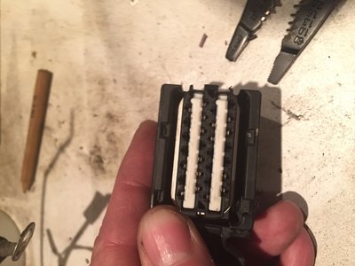
The upper casing can be removed. Don't be tempted to pry the outer tags out: these are made of brittle, hard plastic, and they will snap. Guess how I found that out :roll: The upper casing can be pushed in, and the barbs pried out to reveal the wire insertion into the plug.
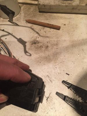
The upper cover of the C0159 plug can be pressed in, so barbs clear main plug body
Each of the connectors has a barb - so they don't just pull out. But luckily, there is a locking mechanism that can be unlocked from the plug-side of the connector: put it to the opposite side, and the wire and the female connector pins can be pulled out. This won't make any sense - so I shall try to remember to take some pictures of the dissected C0159 connector - it may prove of use to others! :) Edit - pictures added below:
Underside of the C0159 plug. Note two white coloured inserts - this is the secondary locking mechanisms that prevent the female connector pins from falling out.
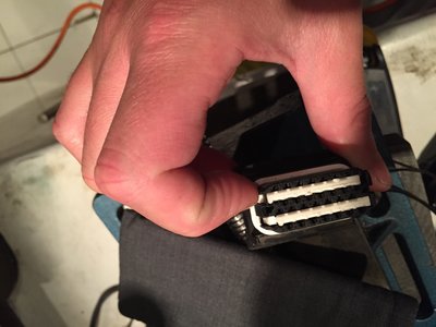
To lock or unlock, push the white locking mechanism from side to side.
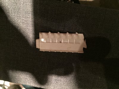
Here I have removed the locking mechanism - see how little "L"-shaped bays are molded in? Pushing it to one side locks the connector barb in position, but to the other opens a channel where the pin can be withdrawn.

Having mastered the technique on the now completely destroyed connector, I could safely re-wire the C0159 to suit my application :D

Just want to show another picture now - the now redundant MEMS1.9 connector with the cables cut to splice in the MEMS3 C0157 connector :) I've got just a couple more wires to solder (the three earth cables, and work out which wire to pick up the switched live power), and it is nearly job done before moving onto grafting these MEMS1.9 plugs to the MEMS3 engine loom :)
IMG_2279.JPG

User avatar
Rob Bell
Committee Member
Posts: 14425
Joined: Tue Oct 02, 2007 2:36 pm
MGF Register Region: South East
Model of Car: MGF 1.8i + MGF Shed!

Re: Motorbike throttle bodies on a K-series - and run on MEMS3?

Post by Rob Bell » Mon Oct 19, 2015 11:02 am

Not sure if anyone is reading, but now wondering why no one simply grafts on a MEMS3 connector to the MEMS1.9 loom and have done with it? I guess the MEMS3 sensors may not be compatible with the earlier versions???

User avatar
Rob Bell
Committee Member
Posts: 14425
Joined: Tue Oct 02, 2007 2:36 pm
MGF Register Region: South East
Model of Car: MGF 1.8i + MGF Shed!

Re: Motorbike throttle bodies on a K-series - and run on MEMS3?

Post by Rob Bell » Mon Oct 19, 2015 11:38 am

Note to self: Just looking at the diagrams - ambient engine bay temperature appears to be connecting to C0159-34 C0914-21 (engine bay loom - slate grey/white wire) - so will check this, but looks reassuring! :D

User avatar
Rob Bell
Committee Member
Posts: 14425
Joined: Tue Oct 02, 2007 2:36 pm
MGF Register Region: South East
Model of Car: MGF 1.8i + MGF Shed!

Re: Motorbike throttle bodies on a K-series - and run on MEMS3?

Post by Rob Bell » Mon Oct 19, 2015 1:05 pm

The next phase will be sorting out the wiring with the body loom to engine loom connectors. Details of the two black and one blue MEMS1.9 connectors above. The MEMS3 green (C0203) and grey (C0162) connectors are as follows:

Green C0203 (C0449)
MEMS3 Green body loom connector C0203.png
SW - engine bay ambient temperature
KB - Sensor earth
UY - Lambda (post cat)
R - Air con relay
GY - Reversing light (from fuse box)
GN - Reversing light (to bulbs)
NY - Charge warning light
GU - Coolant temperature gauge
NU - Oil temperature
WO - Speed transducer (from gearbox sender to electronic speedo)
WG - Gearbox warning lamp
U - Trinary switch
GB - Lambda (post cat)
UR - Lambda (post cat)


Grey C0162 (C0448)
MEMS3 Grey body loom connector C0162.png
BU - CVT gearbox starter inhibitor
BR - CVT gearbox starter inhibitor
UW - CVT gearbox selector
UR - CVT gearbox selector
UY - CVT gearbox selector
US - CVT gearbox selector
WN - Oil pressure warning
NK - Sensor power (MEMS3 remote relay module) --> SJ6
NK - Sensor power (MEMS3 remote relay module) --> SJ5
NR - Starter from remote relay

User avatar
Rob Bell
Committee Member
Posts: 14425
Joined: Tue Oct 02, 2007 2:36 pm
MGF Register Region: South East
Model of Car: MGF 1.8i + MGF Shed!

Re: Motorbike throttle bodies on a K-series - and run on MEMS3?

Post by Rob Bell » Mon Oct 19, 2015 1:40 pm

Thinking aloud for a moment, it looks as though the two looms need to be grafted just after that nexus point ahead of the large engine cable bundle... hopefully most of the colours will match up this time!

User avatar
Rob Bell
Committee Member
Posts: 14425
Joined: Tue Oct 02, 2007 2:36 pm
MGF Register Region: South East
Model of Car: MGF 1.8i + MGF Shed!

Re: Motorbike throttle bodies on a K-series - and run on MEMS3?

Post by Rob Bell » Mon Oct 19, 2015 5:21 pm

From above, but striking out the bits I don't need:

Green C0203 (C0449)
MEMS3 Green body loom connector C0203.png
SW - engine bay ambient temperature
KB - Sensor earth
UY - Lambda (post cat)
R - Air con relay
GY - Reversing light (from fuse box)
GN - Reversing light (to bulbs)
NY - Charge warning light
GU - Coolant temperature gauge
NU - Oil temperature
WO - Speed transducer (from gearbox sender to electronic speedo)
WG - Gearbox warning lamp
U - Trinary switch
GB - Lambda (post cat)
UR - Lambda (post cat)


Grey C0162 (C0448)
MEMS3 Grey body loom connector C0162.png
BU - CVT gearbox starter inhibitor
BR - CVT gearbox starter inhibitor
UW - CVT gearbox selector
UR - CVT gearbox selector
UY - CVT gearbox selector
US - CVT gearbox selector

WN - Oil pressure warning
NK - Sensor power (MEMS3 remote relay module) --> SJ6
NK - Sensor power (MEMS3 remote relay module) --> SJ5
(not needed as contained within the MRU wiring - will need the NK feeds connecting through to main MEMS3 engine loom harness though)
NR - Starter from remote relay (starter relay wiring self-contained within in MEMS1.9 connector/ MRU subloom)

So that looks like around 6 wires from the MEMS3 loom to the body connectors:
GY - Reversing light (from fuse box) --> C120-5
GN - Reversing light (to bulbs) --> C120-6
NY - Charge warning light --> C120-7
GU - Coolant temperature gauge --> C120-9
NU - Oil temperature --> C127-7
WN - Oil pressure warning --> C127-8


The remaining cables will be from the MRUs to the MEMS3 loom:
Input/Output for the "Main" relay --> x2 NK cables (for stepper motors and injector drivers)
Output for the starter relay --> NR cable (to starter motor)
Input/Output for the fuel pump relay --> but already contained within the MEMS1.9 wiring loom to MRU

Plus:
C120-1: Ignition signal to ECU (W) [via MRU (to energize the main and fuel pump relays)]


Lambda heater relay will be unused.

User avatar
Rob Bell
Committee Member
Posts: 14425
Joined: Tue Oct 02, 2007 2:36 pm
MGF Register Region: South East
Model of Car: MGF 1.8i + MGF Shed!

Re: Motorbike throttle bodies on a K-series - and run on MEMS3?

Post by Rob Bell » Mon Oct 19, 2015 6:04 pm

The above shouldn't be too onerous to connect. Mostly main engine loom to MEMS1.9 connector subloom by the looks of things. :)

But I've spotted a problem with the C0159 MEMS3 small body loom connector wiring:

Image

There is an important difference between MEMS1.9 and MEMS3. MEMS3 needs a permanent power supply, whereas MEMS1.9 is switched (via the main relay, and through the NK power distribution circuit). Therefore, C0159-80 is a PERMANENT live not, as I had envisaged, a switched live (NK). Therefore I will need to splice into one of the main power (N) cables, preferably with a 15A in-line fuse (a function performed by a dedicated power supply from the fuse box via a 15A fuse in MEMS3-equipped cars).

Will need to tap into one of the main brown power cables - unfortunately there are no splice joints on the engine side of the C0121 plug... :|

Amended connector summary therefore:
MEMS1.9 to MEMS3 colour code comparison - ammended.png

User avatar
Charless
Posts: 2364
Joined: Tue Oct 09, 2007 1:52 pm
MGF Register Region: South Coast
Model of Car: 96 Mpi, 99 VVC
Location: Chilbolton

Re: Motorbike throttle bodies on a K-series - and run on MEMS3?

Post by Charless » Mon Oct 19, 2015 8:04 pm

Yes, some of us are following this magnum opus - and thanking our lucky stars that we don't have to go to such lengths to stay mobile yet.
I recently had to replace a MEMS 1.9 ECU to keep one on the road - 1.9s are in increasingly short supply; whereas there are loads of MEMS 3 units about, apparently more reliable. You have had a busy day but great for the rest of us to have it all recorded! Thank you :)

User avatar
talkingcars
Posts: 5766
Joined: Tue Mar 09, 2010 10:44 pm
MGF Register Region: South East
Model of Car: mk1 VVC
Location: West Sussex
Contact:

Re: Motorbike throttle bodies on a K-series - and run on MEMS3?

Post by talkingcars » Mon Oct 19, 2015 8:23 pm

Converting my MEMS 2.0 VVC to MEMS 3 VVC is at the top of my jobs to do when I've run of jobs list.

I don't know about you Rob but I love cross matching looms.

I've managed to get terminals out of these sockets, just don't ask me to try and explain how, the one I can't do is the white plug for the rotary coupler.
Home to black Alfa 159 3.2 V6 Q4, blue MGZR160, green MGF VVC and grey MGF 1.8i, and red MG Maestro T16.

MGF chatting on the Register and at http://www.the-t-bar.com

Post Reply